Transmission line model depicts the microstrip antenna by two slots of width W and height h seprated by transmission line of length LThe microstrip is a non homogeneous of two dielectricstypicallysubstrate and the air Most of the electric field lines reside some part in the air. Similarly a -200 phase shift is achieved by taking length of delay line 464 mm in left side as in Fig2.
![]()
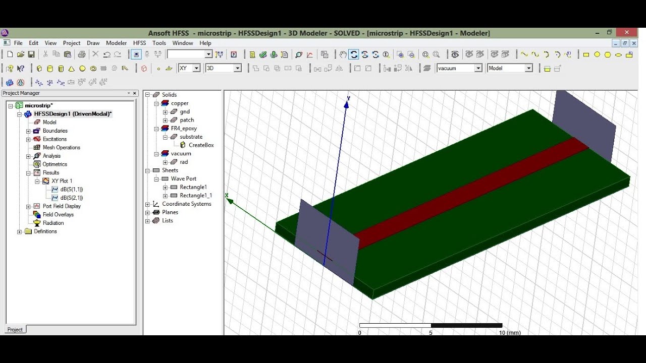
Microstrip Transmission Line On Hfss All Reports S Parameters Imp
Wave port with 2 modes.

. Aperture coupled microstrip antenna block diagram. But still s21 is. The designed 2x1 and 4x1 RMSA arrays were fed by the parallel feeding structure.
Even-odd mode analysis. Creating the Microstrip We are going to make the substrate aka dielectric layer ground plane and copper trace conductor for a microstrip line. DESIGN OF MICROSTRIP LOPWASS FILTER.
The basic model of a microstrip transmission line is shown in Fig. Required dimensional adjustments when changing substrate materials and. Transmission Line Design and Simulation of 50 Ω microstrip line using HFSS TDT01.
A Microstrip transmission line displaying quasi-TEM mode of propagation. In this tutorial a microstrip transmission line is simulated with Designer. How Interconnects Work.
The designed single element 2x1 and 4x1 rectangular microstrip antennas were simulated in Ansoft high frequency structure simulator HFSS version 150 software. Third order stepped impedance low pass microstripfilter has been designed and analyzed using Ansoft HFSS software at 1GHz frequency on Duroid substrate. Microstrip transmission line fed patch antenna.
A microstrip line consists of a conductor of width W a dielectric substrate of thickness d and permittivity ε r. In this video a 50 Ω microstrip line is designed and its step by step process is explained. Filter is designed and analyzed in Ansoft Designer.
Coaxial to microstrip CPW transition design. Rename it to 50 Ohm Line. .
A 200 phase shift is achieved by taking length of delay line 504mm in right side as in Fig1. The microstrip line will be designed on a substrate with a dielectric constant of 102 and a height of 127 mm at 50 GHz. First verify the microstrip line.
Providing small delay line for the length of transmission line feeding in 2 x 1 Microstrip antenna we obtained different phase shift values. Using CST Studio suite or ANSYS HFSS computer simulation. Lumped elements are converted into microstrip line using Ricahrds transformation method.
I used line calc of ADS for calculation of dimensions ie. I applied lumped port of hfss with integration line and 50 ohm impedance. Project-Insert HFSS Design 2.
Raghavan on 30th may 2014 TRANSMISSION LINES MICROWAVE ENGG. The width of the microstrip is designed for 50 Ω and the length for a 180 degree phase delay. Wave port of microstrip lines.
An important component in microstrip-to-slotline circuitry is the well matched microstrip-to-slotline transition with low insertion loss. Coplanar WaveguidesModeling and Simulation of Electromagnetic Devicesmp4 Slotted Line SimulationMagic of Lamda by prof. Hence the microstrip described in Table 41 was simulated using two main microwave circuit simulators.
The main results of the designed antennas were compared in terms of gain and return loss. Substrate thickness 16 mm and. The upper limit is set by production tolerances while the lower limit is set by the appearance of high-er-order modes.
Insert a New Design. Microstrip transmission line structures have been shown to be not fully TEM and are considered quasi-TEM. Microstrip transmission lines in combination with slotlines plays a very important role in the design of Microwave Integrated Circuitry.
The link for the online calculator used is httpswwwemtalkc. Stripline transmission linerequires three layers of conductors where the internal conductor is commonly called the hot conductor while the other two always connected at signal ground are called cold or ground conductors. I want to design a microstrip line in hfss with fr4 substrate.
Microwave design microstrip line design in hfss 13 part1 youtube april 29th 2018 - a simple microstrip transmission line is design here please on the subtitles captions for better understanding project 1 rectangular waveguide hfss may 2nd 2018 - i insert an hfss design into a project 1 on the 22 25. There are three types of losses that occur in microstrip lines. The green lines represent the E-field and purple lines the H-field.
The Ansoft High Frequency Structure Simulator HFSS is a full-wave electromagnetic EM software package for. Research as designed in Atwater has been conducted to develop mathematical closed-form expressions. Impedance range of a microstrip line is 20 to 120 V.
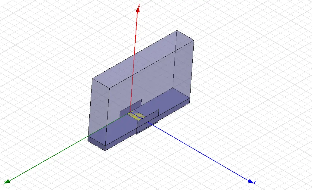
Ansofts High Frequency Structure Simulator HFSS and. Terminate the transmission line in its characteristic impedance when the one-way propagation delay of the PCB track is equal to or greater than one-half the applied signal risefall time whichever edge is faster. To do this we will make three boxes in HFSS and then designate the appropriate dimensions and material for each box.
Introduction to Transmission Lines Microstrip vs. The structure will exhibit dispersion across frequency and across any considerable physical length. HELLO can any one tell where is mistake.
Transmission line ports will be expressed in terms of. Probe fed patch antenna. Design a 20-dB microstrip coupled line operating at 242 Ghz.
From 23GHz specified in nominal HFSS design to 24GHz for wireless communication applications. Con-Microstrip Lines DESIGN FEATURE H hh e 96 e 20 Wh 2 Wh 2 123456789 Effective dielectric constant 12 13 23. For example a 2 inch microstrip line over an Er 40 dielectric would have a delay of about 270 ps.
50 Hz 93mm 10 MHz 21um 100 MHz 66um 1 GHz 21um 10 GHz 066um.

Hfss Design Of Microstrip Patch Antenna Download Scientific Diagram
Microstrip Line Design In Hfss 13 Part1 Use Captions Cc Youtube
Microstrip Antenna Design With Ansys Hfss 12cad Com

3 A Simulation Setup For The Analysis Of A Microstrip Line And B Download Scientific Diagram

Microstrip Line Design In Hfss Part2 Youtube

Analysis And Design Of Rectangular Microstrip Patch Antenna Using Hfss Semantic Scholar

Three Band And 2 Element Antenna Array With Hfss Download Scientific Diagram
Design And Simulation Of 50 W Microstrip Line Using Hfss Youtube
0 comments
Post a Comment